I am building up the mDrive replacement, well... I have found some issues that I Couldn't see before. Not very problematic actually but I would like to work on them.
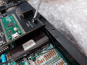
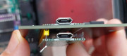
Firstly... the first board placed on MDV1... MUST be underboard fitted. Why? because in other case, the chassis will choke with the RasbPi USB connector... That's why, on the photos published by Dr. Gusman (the author) first mDrive is under the PCB (hidden). That's why.
Some pictures:
It is solved as I described it before (but I didn't know why he did it, now I know it).
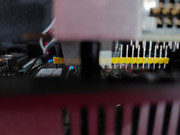
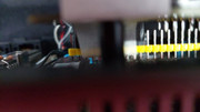
Some pictures to give the idea:
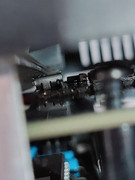
it may be with female and male connector just... be aware with Hermes IC, it fits but... not to much so some adjustment of pin length could improve it. Just in case you add female connector under PCB. Next photos shows results:
Last point:
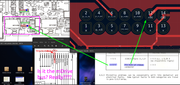
After opening it and removing the mDrive... I can tell that voltage regulator on PCB emulator doesn't need to stay on that way, could be settled vertically on the bottom side. Without bothering cables at all. There is nothing. I would like to work in a version that set the regulator in another place.
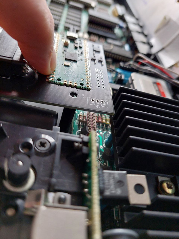
Also move the connector IDC to the left to get it over the PCB connector. Even to replace the U1 (voltage regulator) where the head of J2 is now.
Some... maybe tricks that I see while writing this post... it seems to me that we don't need IDC connector at all. Morveoer when we don't want to replace original connector on QL board. Some pins male 2x7 with those cables from Arduino to directly the PCB connector should do the work nicely. Ouh yeah!
Well.. that's all folks. Some experience and ideas share
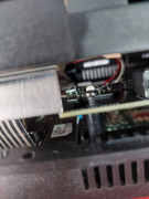
Edit:
I forgot the screw from mDrive (left-corner side) doesn't match with the PCB, get too high, it needs something to get properly fixed.